RTL8367S SGMII/HSGMII on the Mercusys MR80X v2.20 (IPQ5018): reverse-engineering a switch SerDes for mainline
Summary
The four LAN ports of the MR80X v2.20 did not work under OpenWrt because the RTL8367S is wired to the IPQ5018 over the SerDes, and rtl8365mb only implemented RGMII. I captured the real register sequence by chainloading my own U-Boot ahead of the stock one and instrumenting its MDIO writes, then implemented SGMII and HSGMII as a phylink PCS, keeping the embedded DW8051 in reset instead of loading firmware into it. Merged into net-next, landing in 7.3.
The story
I had an Asus RT-AC66U at home as an AP until its vendor firmware went end of support. I did not want to keep running an unmaintained device, so I flashed OpenWrt on it, and ran straight into the Broadcom problem: OpenWrt's own hardware page for the device warns that devices with Broadcom WiFi chipsets have limited supportability because of the lack of FLOSS drivers, and with b43 the radios were not usable for what I wanted.
So I went looking for a replacement: WiFi 6, 2x2 MIMO, and supported by OpenWrt. One candidate was the Xiaomi AX3000T, but buying one is a lottery between the MediaTek variant and the Qualcomm IPQ5018 variant, and on top of that it would have shipped from China with a one to two month lead time. There was a much cheaper router available in a local shop, so I went to look at it.
The hardware revision on the box said Model: MR80X(US) Ver:2.20. OpenWrt only supported the v3, which is MediaTek. I left the shop without buying anything and spent the rest of the day reading. I found a teardown blog post that told me which SoC and switch the board used and had photos of the inside, which was enough to convince me it was worth trying. It did not say anything about secure boot, which was the one thing that would have stopped me cold.
https://www.drejo.com/blog/mr80x-teardown-openwrt/
The next day, 7 May 2026, I went back and bought it. Around 40 to 45 USD. The plan, if it did not work out, was to resell it to a friend.
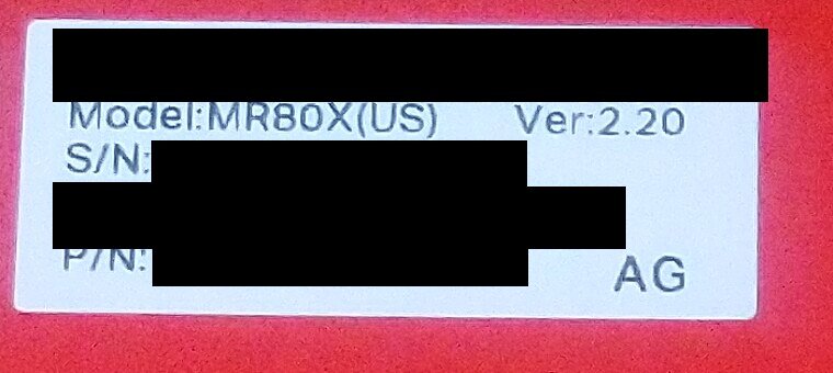
The label on the box. Ver:2.20 is the whole problem: OpenWrt supported v3, which is a different SoC. Serial redacted.
The stock firmware is an OpenWrt fork with TP-Link's own userspace on top (Mercusys is their sub-brand). The web UI does what an average user needs and nothing more: no VLAN configuration, no multiple APs on the same band, none of the things I bought the device for.
The specs I was working with: IPQ5018, 256 MB of DDR, a 128 MB GigaDevice F50D1G41LB SPI NAND, the 2.4 GHz radio inside the SoC and a QCN6122 for 5 GHz, and an RTL8367S handling the front ports. The RF chains are soldered coax pigtails to the board.
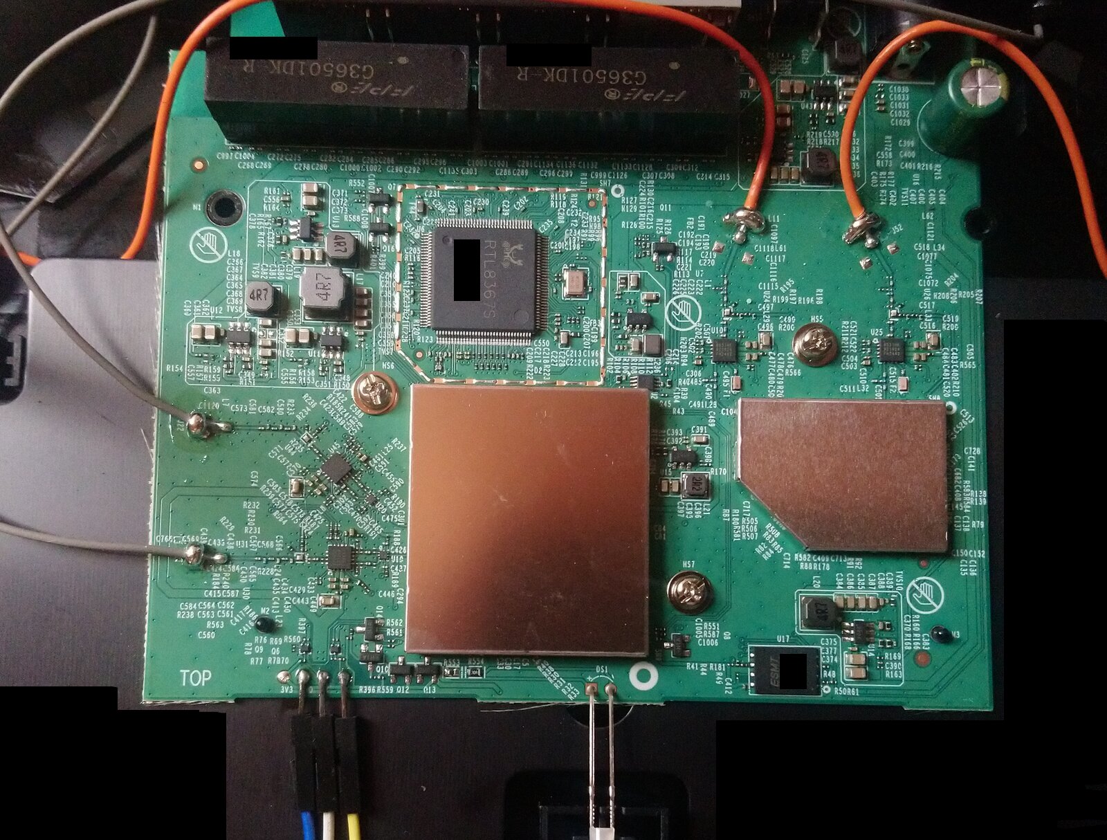
Top side. The two shield cans cover the IPQ5018 (left) and the QCN6122 (right); the RTL8367S sits above them, the magnetics and the four front ports along the top edge. The orange and grey wires are the RF pigtails, soldered rather than connectorized. Bottom left is the UART header.
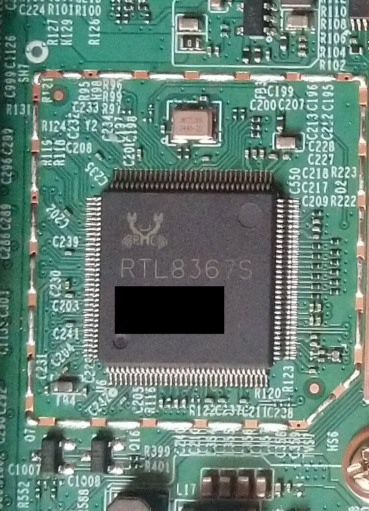
The switch this post is about.
First contact: UART, U-Boot and a dump before the first boot
The board has a 4-pin UART header, with the RX and TX series resistors already populated. I found ground with a multimeter and soldered three jumpers rather than the adapter directly, so I could swap RX and TX if I got them backwards. 115200 8N1.
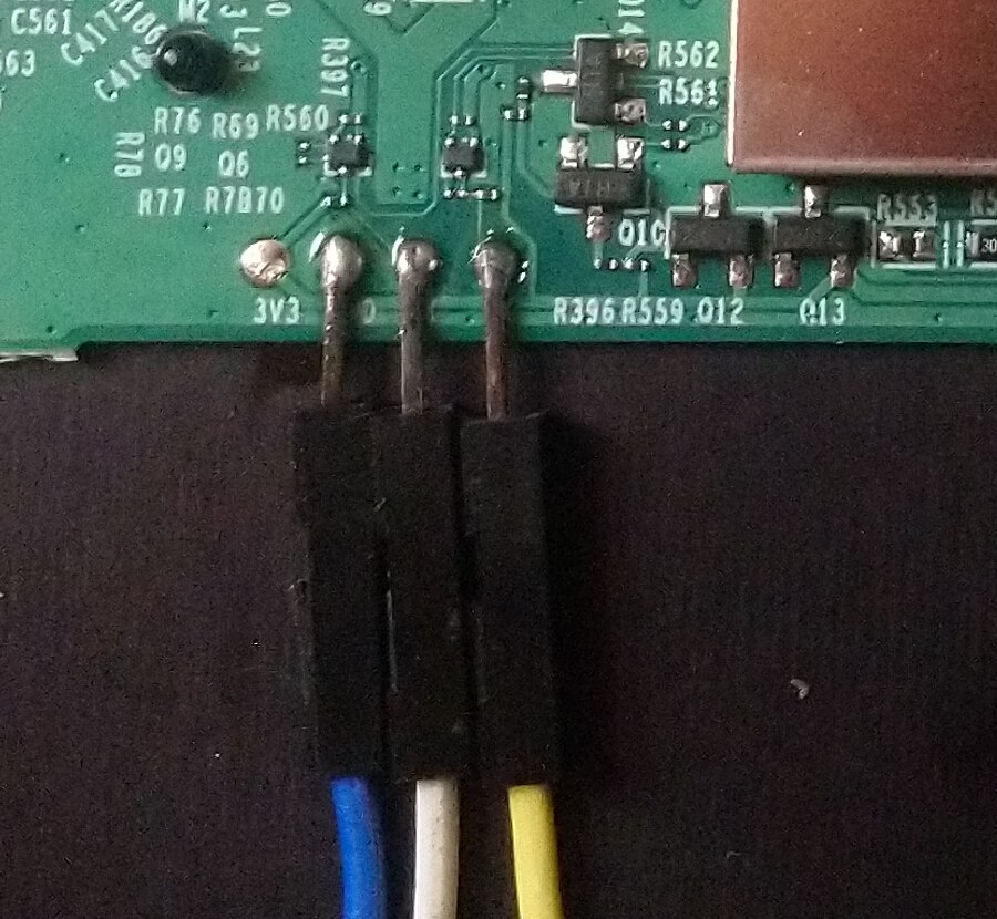
The header is 3V3, GND, RX, TX. 3V3 stays unpopulated - the adapter supplies its own level reference and the board is powered normally. Blue is ground.
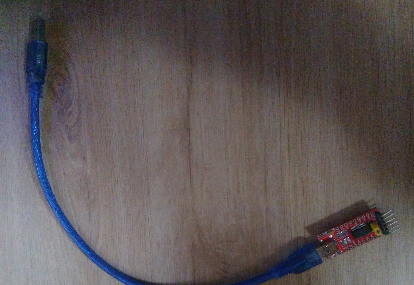
The other end.
Before powering it up for the first time as a user, I wanted a dump of the flash in its factory state, so that nothing had been written to it yet. Interrupting the boot needed no password and no timing trick: any key at the right moment, ESC in my case, and I had the IPQ5018# prompt. That prompt existing at all, and later being able to run my own OpenWrt build for the SoC without complaint, is what told me there was no secure boot on this unit.
I dumped the NAND in two halves, nand read into RAM and then tftpput to my machine, joining them on the PC. Two 64 MB files, nand_part1.bin and nand_part2.bin, both timestamped 7 May 15:21. Then I did the first boot with the UART attached, watched the log, and set the initial password in the web UI.
Running binwalk over the joined image gives the expected layout: an ARM 32-bit ELF at 0x2800, two ARM64 ELFs at 0x180000 and 0x280000, a gzipped dtb_combined.bin, and then a long list of UBI images starting at 0x640000.
-------------------------------------------------------------------------------------------------------------------------------------------------------------------------------------------------------------------
DECIMAL                            HEXADECIMAL                        DESCRIPTION
-------------------------------------------------------------------------------------------------------------------------------------------------------------------------------------------------------------------
10240                              0x2800                             ELF binary, 32-bit executable, ARM for System-V (Unix), little endian
1572864                            0x180000                           ELF binary, 64-bit executable, ARM 64-bit for System-V (Unix), little endian
2621440                            0x280000                           ELF binary, 64-bit executable, ARM 64-bit for System-V (Unix), little endian
3670016                            0x380000                           ELF binary, 32-bit shared object, ARM for System-V (Unix), little endian
4056024                            0x3DE3D8                           SHA256 hash constants, little endian
4137528                            0x3F2238                           CRC32 polynomial table, little endian
4138552                            0x3F2638                           CRC32 polynomial table, little endian
4260048                            0x4100D0                           gzip compressed data, original file name: "dtb_combined.bin", operating system: Unix, timestamp: 2024-09-20 03:15:40, total size: 5158 bytes
6553600                            0x640000                           UBI image, version: 1, image size: 27525120 bytes
34078720                           0x2080000                          UBI image, version: 1, image size: 2752512 bytes
36831232                           0x2320000                          UBI image, version: 1, image size: 2752512 bytes
39583744                           0x25C0000                          UBI image, version: 1, image size: 2752512 bytes
42336256                           0x2860000                          UBI image, version: 1, image size: 2752512 bytes
45088768                           0x2B00000                          UBI image, version: 1, image size: 2752512 bytes
47841280                           0x2DA0000                          UBI image, version: 1, image size: 2752512 bytes
94633984                           0x5A40000                          UBI image, version: 1, image size: 2752512 bytes
97386496                           0x5CE0000                          UBI image, version: 1, image size: 2097152 bytes
99483648                           0x5EE0000                          UBI image, version: 1, image size: 1703936 bytes
101187584                          0x6080000                          UBI image, version: 1, image size: 1441792 bytes
102629376                          0x61E0000                          UBI image, version: 1, image size: 1441792 bytes
104071168                          0x6340000                          UBI image, version: 1, image size: 1179648 bytes
105250816                          0x6460000                          UBI image, version: 1, image size: 6291456 bytes
-------------------------------------------------------------------------------------------------------------------------------------------------------------------------------------------------------------------

Analyzed 1 file for 85 file signatures (187 magic patterns) in 359.0 milliseconds
The MTD layout, sixteen partitions, has the usual Qualcomm boot chain (0:sbl1, 0:mibib, 0:qsee, 0:devcfg, 0:cdt, 0:appsbl, 0:art) and then two 42 MB rootfs partitions, rootfs and rootfs_1, for A/B updates, plus tp_data, radio and data.
root@MR80Xv2WRT_SWT:~# cat /proc/mtd
dev:    size   erasesize  name
mtd0: 00080000 00020000 "0:sbl1"
mtd1: 00080000 00020000 "0:mibib"
mtd2: 00040000 00020000 "0:bootconfig"
mtd3: 00040000 00020000 "0:bootconfig1"
mtd4: 00100000 00020000 "0:qsee"
mtd5: 00040000 00020000 "0:devcfg"
mtd6: 00040000 00020000 "0:cdt"
mtd7: 00080000 00020000 "0:appsblenv"
mtd8: 00140000 00020000 "0:appsbl"
mtd9: 00100000 00020000 "0:art"
mtd10: 00080000 00020000 "0:training"
mtd11: 02a00000 00020000 "rootfs"
mtd12: 02a00000 00020000 "rootfs_1"
mtd13: 00840000 00020000 "tp_data"
mtd14: 00440000 00020000 "radio"
mtd15: 00080000 00020000 "data"
One thing I noticed later, when I could look inside the filesystem: the vendor userspace is 32-bit. busybox is an ELF32 ARM EABI5 executable against musl, and the kernel modules are ELF32 relocatable as well, so the whole thing is built for ARMv7 on a 64-bit SoC.
The kernel is 4.4.60, built September 2024, and U-Boot is 2016.01 from the same date. The FIT image in the kernel volume carries 24 device trees for the whole IPQ5018 reference board family; the one this board uses is fdt@mp02.1, IPQ5018/AP-MP02.1, which the boot log confirms.
| # | node | size | model |
|---|---|---|---|
| 1 | fdt@mp03.1-c2 | 59696 | IPQ5018/AP-MP03.1-C2 |
| 2 | fdt@mp03.3-c2 | 59919 | IPQ5018/AP-MP03.3-C2 |
| 3 | fdt@mp03.5-c2 | 60328 | IPQ5018/AP-MP03.5-C2 |
| 4 | fdt@emulation-c3 | 55085 | IPQ5018/MP-EMU |
| 5 | fdt@db-mp02.1 | 58276 | IPQ5018/DB-MP02.1 |
| 6 | fdt@db-mp03.3-c2 | 59101 | IPQ5018/DB-MP03.3-C2 |
| 7 | fdt@mp02.1 | 60096 | IPQ5018/AP-MP02.1 |
| 8 | fdt@db-mp03.3-c3 | 58344 | IPQ5018/DB-MP03.3 |
| 9 | fdt@mp03.1-c3 | 58883 | IPQ5018/AP-MP03.1-C3 |
| 10 | fdt@mp03.4-c1 | 58409 | IPQ5018/AP-MP03.4-C1 |
| 11 | fdt@mp03.5-c1 | 59563 | IPQ5018/AP-MP03.5-C1 |
| 12 | fdt@tb-mp04 | 59122 | IPQ5018/TB-MP04 |
| 13 | fdt@mp03.6-c1 | 64158 | IPQ5018/AP-MP03.6-C1 |
| 14 | fdt@db-mp03.1 | 59426 | IPQ5018/DB-MP03.1 |
| 15 | fdt@emulation-c2 | 54514 | IPQ5018/MP-EMU |
| 16 | fdt@emulation-c1 | 55048 | IPQ5018-EMULATION-C1 |
| 17 | fdt@db-mp03.3 | 58328 | IPQ5018/DB-MP03.3 |
| 18 | fdt@mp03.6-c2 | 64923 | IPQ5018/AP-MP03.6-C2 |
| 19 | fdt@sod | 57331 | IPQ5018/AP-MP03.1 |
| 20 | fdt@mp03.1 | 58927 | IPQ5018/AP-MP03.1 |
| 21 | fdt@db-mp03.1-c2 | 60199 | IPQ5018/DB-MP03.1-C2 |
| 22 | fdt@mp03.4-c2 | 59903 | IPQ5018/AP-MP03.4-C2 |
| 23 | fdt@mp03.3-c3 | 59258 | IPQ5018/AP-MP03.3-C3 |
| 24 | fdt@mp03.3 | 59150 | IPQ5018/AP-MP03.3 |
No root
The first surprise was that the password I had set in the web UI did not work for the root login on the serial console. I had assumed they were the same credential. They are not.
That left me without a shell on a device I had just bought specifically to study. I spent a while looking for a way in through the web UI, either a command injection or a path traversal, and did not find one. The API was reasonably well defended: the places where I tried to smuggle something in (a URL field when adding a VPN, and a couple of parameters that end up in a command) were sanitized, and I did not manage to get a string through. I did not test everything, and this is an observation about my attempts, not a claim about the firmware's security.
The web UI is Lua. I extracted it from the image expecting to read it and instead found compiled bytecode, and when I tried to decompile it, obfuscated bytecode. So I went at it sideways, and this turned out to be the most entertaining part of the whole project: the vendor ships its own liblua.so.5.1.4, so I put it on an Orange Pi 5 Pro (ARM CPU, so the library runs natively), compiled trivial expressions like 1+1 with it, compiled the same expressions with upstream Lua 5.1.4, and diffed the output. The obfuscation turned out to be a permutation of the instruction table: same VM, opcodes renumbered. Compile, compare, identify one opcode, write it down, repeat. Once the mapping was complete the bytecode decompiled normally.
I am not publishing the mapping table. The method is the interesting part; the table is a ready-made tool against one specific product.
What made the effort worth it was the flash update script. It showed that an image is accepted either signed by TP-Link, or unsigned if the headers are exactly right. TP-Link seems to leave that path open deliberately, and other Mercusys devices in OpenWrt already use it, so I was not the first to find it. I adapted the same approach for my own images later.
In parallel I looked at where credentials live. The shadow in the factory rootfs contains no hashes at all: the password fields are x, *, or empty. Nothing to crack. Whatever the console root credential is, it is not in there, and I never went back to find out where it comes from. That remains an open question about this firmware.
I also poked at tp_data, which is the UBIFS volume that holds the device's MAC (default-mac), device-id, pin, product-info, the HTTPS certificate and user-config. user-config is the interesting one, and it is wrapped in several layers: AES-256-CBC on the outside, zlib, a 16-byte header followed by a standard TAR, and inside the TAR one particular file (ori-backup-user-config.bin) is encrypted and compressed again, with plain XML at the bottom. The master key is embedded in the firmware, in the Lua files. My idea was to inject something into that XML that would be loaded on the next boot and run a command for me, but it needed more analysis of the surrounding code than it was worth, and I abandoned it. When I did modify it, all I changed was the hashed web UI password, which was not what I wanted.
There is also an SSH service listening on a high port on the LAN interface in stock firmware. I tried it with the usual candidates and with the password I had set in the web UI, and none of them were accepted.
ssh -p20001 -o HostKeyAlgorithms=+ssh-rsa -o PubkeyAcceptedAlgorithms=+ssh-rsa root@192.168.1.1 "sh -i"
Getting root
The route that worked was blunt: modify the root filesystem offline and write it back from U-Boot, where I already had full access to the flash.
From the extracted rootfs partition, binwalk gives a UBI image containing two volumes, img-1067554868_vol-kernel.ubifs and img-1067554868_vol-ubi_rootfs.ubifs. I pulled the kernel out of the FIT with dumpimage, extracted device tree number 7 (the AP-MP02.1 one), and unpacked the squashfs with unsquashfs. Then I emptied the password fields for root and admin in both passwd and shadow, rebuilt the image, loaded it over TFTP into RAM and wrote it to the rootfs partition. No ubi write, the whole partition.
Before that I had tried the cleaner-looking approach of booting a modified root filesystem as a ramdisk, which is what MINE_rootfs_ramdisk.uimg and mod_rootfs.uimg in my TFTP directory are, both from 16 May. That never worked. The FDT carries a hardcoded command line (console=ttyMSM0,115200,n8 rw init=/init), so I rebuilt the device tree to get my own bootargs, wanting a shell without /init running, to see what it was doing before it got in my way. What I ran into is that /init mounts the UBIFS volumes itself and then panics if the situation is not what it expects, so a ramdisk root would have needed the mounting done by hand. I did not get useful answers out of that path, and it stopped mattering once the flash write worked.
After the write, typing root on the serial console dropped me straight into a shell. That was 16 May, nine days after buying the device.
md5sum /lib/firmware/IPQ5018/board.bin
MR80X login: ^C
Please press Enter to activate this console.
MR80X login: root


BusyBox v1.19.4 (2024-09-20 11:58:16 CST) built-in shell (ash)
Enter 'help' for a list of built-in commands.
With root I could read the running system: the firmware files the radios use, the register state of the switch, and everything under /dev and /sys that I had been guessing about until then.
The radios
Getting the radios up under OpenWrt was, by comparison, quick. I was targeting ath11k on an OpenWrt SNAPSHOT (r32802-f505120278, kernel 6.12.94, aarch64).
The vendor ships raw board files, one per radio, and the stock rootfs carries two copies of them. There is a baseline set at the runtime path, /lib/firmware/IPQ5018/WIFI_FW/, and there are per-region overlay trees at the top of the filesystem, one directory per region and model:
/US/MR80X/default/lib/firmware/IPQ5018/WIFI_FW/bdwlan.b24
/US/MR80X/default/lib/firmware/IPQ5018/WIFI_FW/qcn6122/bdwlan.b60
/EU/MR80X/default/lib/firmware/IPQ5018/WIFI_FW/bdwlan.b24
...
US and EU each hold MR1800X, MR3000X, MR70X and MR80X. /init copies the right one over the runtime path at boot - that is what the boot log means by run_init_for_tp_qca(): Copy US Filesystem !!!!!.
This matters more than it looks. The overlay files and the baseline files have the same names and different contents: /lib/firmware/IPQ5018/WIFI_FW/bdwlan.b24 and /US/MR80X/default/.../bdwlan.b24 are two different 131072-byte blobs, and the US and EU copies differ from each other again. Take the file from the wrong path and everything still boots, with the wrong region's calibration.
The radio-to-file pairing comes from the boot log - Boardid from dts:24,FW:ff then BDF IPQ5018/bdwlan.b24 size 131072 for the SoC radio, Boardid from dts:60,FW:ff then BDF qcn6122/bdwlan.b60 for the QCN6122 - and the board id in each name is the dts board id, not a version. The ones to ship are the ones from the region overlay, after the copy.
ath11k does not want raw board files, it wants a board-2.bin container keyed by a name the driver builds at runtime from the bus, the QMI IDs and the calibration variant string from the device tree. I used ath11k-bdencoder from qca-swiss-army-knife to wrap each board file, with variant=Mercusys-MR80X-v2 matching the qcom,ath11k-calibration-variant line in my DTS. Two separate containers, one per radio, because they land in different firmware directories and must not be merged into one file.
NAME="bus=ahb,qmi-chip-id=0,qmi-board-id=255,variant=Mercusys-MR80X-v2"
qmi-board-id=255 is the FW:ff from the boot log, and the variant string is the qcom,ath11k-calibration-variant line from the DTS. Reading a container back is how I checked I had wrapped the file I meant to wrap - the board MD5 is the MD5 of the raw bdwlan blob, so it identifies which of the same-named copies went in:
python3 ath11k-bdencoder -i board-mercusys_mr80x.ipq5018
FileSize: 131180
FileCRC32: ddb57ab0
FileMD5: 4cd72d2fcac767f8d71e01a44c268ddf
BoardNames[0]: 'bus=ahb,qmi-chip-id=0,qmi-board-id=255,variant=Mercusys-MR80X-v2'
BoardLength[0]: 131072
BoardMD5[0]: 69cd1f7c0480fee806c523bc742b1939
Calibration data is handled the way OpenWrt already does it for this platform, extracted from the 0:art partition at boot by the ath11k-caldata hotplug script, with one offset per radio. The MAC address is the exception: on this board it lives in tp_data as default-mac, so it has to be read from there.
# target/linux/qualcommax/ipq50xx/base-files/etc/hotplug.d/firmware/11-ath11k-caldata
)
label_mac=
;;
)
label_mac=
;;
The other IPQ5018 boards in that script take their MAC from 0:appsblenv or from the device tree label. This one reads the binary default-mac out of the mounted tp_data volume and derives the two radio addresses from it.
That was 18 May, two days after root.
Memory is the reason this board is not straightforwardly supportable: 256 MB total, of which the kernel reports about 184 MB usable, and ath11k will OOM on it with default ring sizes. I have a set of reduced ring size macros that has been running for seven days in a real environment with a number of IoT clients without an OOM. That is its own post, along with the results.
The switch: what was missing
I had started poking at the switch four to six days after buying the device, before root, and it went nowhere. With rtl8365mb as it is in mainline and my device tree describing the CPU port as 2500base-x, the failure is immediate and not subtle:
phylink_create() refuses with phylink: error: empty supported_interfaces and returns -EINVAL, dsa_port_phylink_create() reports error creating PHYLINK: -22, and DSA switch setup aborts.
The chip info entry for the RTL8367S declares SGMII and HSGMII on external interface 1, but the driver only implements RGMII, so supported_interfaces ends up empty for a SerDes-connected CPU port and there is nothing for phylink to validate against. On this board the switch is wired to the SoC over the SerDes, which means without those modes there is no CPU port at all and the four front ports are unreachable.
In my device tree the CPU port is port 6 with phy-mode = "2500base-x" and a fixed link at 2500/full, hanging off the second SoC datapath netdev. The SoC side is driven by the IPQ5018 SSDK: the GMAC still runs in its 1000M register mode and the rate comes from the UNIPHY SGMII+ configuration, and since the kernel's fixed-link PHY emulation only goes up to 1000, the conduit netdev's own fixed-link stays at 1000. That mismatch is cosmetic; what matters is the switch-side port description.
&dp2 ;
port@6 ;
The vendor configures the link as HSGMII, so that is what I use as well, but I validated both modes on hardware.
I was stuck here for days. I had no way to observe the MDIO bus (no logic analyzer, and the switch is soldered down), and no register names, which meant even if I could have seen the traffic I would have been staring at anonymous addresses. I was close to giving up on the switch entirely.
The GPL drop and a chainloaded U-Boot
What unstuck it was remembering the paperwork. The Mercusys box came with a pile of leaflets, one of which was a GPL notice telling me to contact them for the source code. I was about to write that email when I searched and found the download page directly.
https://web.archive.org/web/20260611034932/https://www.mercusys.com/en/support/gpl-code/?model=MR80X
I am linking the Web Archive snapshot deliberately. Vendor support pages move, drop models, or change URLs; the snapshot does not.
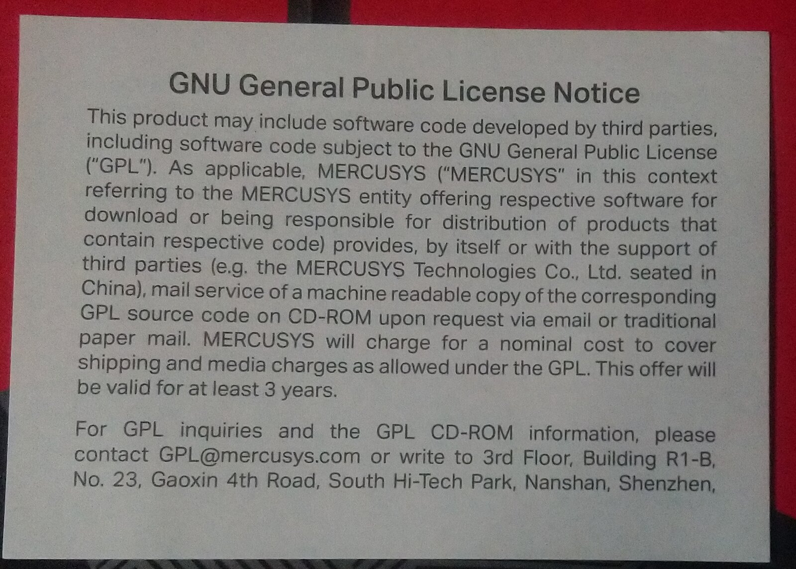
The leaflet. Three years, on CD-ROM, for a nominal cost.
The archive is GPL_MR80Xv2.tar20230105023043.gz, downloaded 17 May. It contains U-Boot 2016.01 and Linux 4.4.60, matching the versions on the device, and it contains the Realtek switch sources.
Having the vendor U-Boot sources meant I could build my own and make it tell me what it was doing. Rather than flashing it over appsbl (which, at the time, I did not know was an option), I built it as an EFI application and chainloaded it from the stock U-Boot with tftp plus bootefi. It did not work on the first try: coming up as a payload rather than as the primary bootloader, parts of the hardware were already initialized, and I had to adjust the code to cope. What I remember clearly is having to reset the Ethernet block so it started from a cold state rather than the one the stock bootloader had left it in.
Then I found the MDIO access function with grep and added logging to it, in both directions. Effectively a software bus sniffer, since I had no way to attach a physical one. The output goes out over UART, tagged so I could tell my lines apart from the vendor's own debug output.
The raw capture is exactly as unhelpful as it sounds. Every switch register access is a short burst of writes to the PHY at MDIO address 0x1d, using registers 0x1f, 0x17, 0x18 and 0x15 as a page/address/data/command window, with reads coming back on 0x19:
[SNIFFER] ipq_mdio_write: mii_id=0x1d, reg=0x1f, val=0xe
[SNIFFER] ipq_mdio_write: mii_id=0x1d, reg=0x17, val=0x13c2
[SNIFFER] ipq_mdio_write: mii_id=0x1d, reg=0x18, val=0x249
[SNIFFER] ipq_mdio_write: mii_id=0x1d, reg=0x15, val=0x3
[SNIFFER] ipq_mdio_write: mii_id=0x1d, reg=0x1f, val=0xe
[SNIFFER] ipq_mdio_write: mii_id=0x1d, reg=0x17, val=0x1300
[SNIFFER] ipq_mdio_write: mii_id=0x1d, reg=0x15, val=0x1
[SNIFFER] ipq_mdio_read:  mii_id=0x1d, reg=0x19
Nothing there says which register is which. So I put a second layer of logging inside the vendor's own helpers, above that window, and printed the arguments symbolically. That is the layer the rest of this post quotes:
[EXT_MODE] id = 1, mode = 9
[DEBUGGER] regValue = 0x6367
[DEBUGGER] type = 1
[DEBUGGER] mode = EXT_SGMII
[DEBUG] option = 1
[DEBUG] redData[0]   = 0x4d7,  0x480
[DEBUG] redDataSB[0] = 0x4d7,  0x480
[DEBUG] redData[2]   = 0x21a2, 0x482
[DEBUG] redDataSB[2] = 0x2420, 0x482
...
[SDS_WRITE] reg: 0x6602, val: 0x2420
[SDS_WRITE] reg: 0x6601, val: 0x0482
[SDS_WRITE] reg: 0x6600, val: 0x00C0
[FORCE_LINK] id = 1, speed = 2, nway = 0
rtk_port_macForceLinkExt_set port 16 ret = 0!!!!!!!!!!!!
[SGMII_NWAY] ext_id = 1, state = 0
Everything in square brackets is mine; rtk_port_macForceLinkExt_set port 16 ret = 0!!!!!!!!!!!! is the vendor's.
Finding the SGMII path was almost accidental. The vendor's own debug print rtk_port_macForceLinkExt_set port 16 ret = 0!!!!!!!!!!!! is distinctive enough that grepping it in the GPL sources landed me directly in the right file, ipq5018_gmac.c, which is Qualcomm integration code under GPLv2. HSGMII was the default there; I added a build-time switch to select SGMII instead, changing the external interface mode, the force mode and the port speed. Getting SGMII to actually come up took some iteration on that combination, but the change itself is small.
The test for "is this actually working" was dhcp at the U-Boot prompt. This is something I picked up while working on the Orange Pi 5 Pro eFUSE support: if DHCP does not complete, the rings are almost certainly not working. It is a cheap end-to-end check that the network device came up correctly, and I could confirm the packets on my PC with tcpdump. When the board pulled an address, I knew I had a live link to instrument.
What all those register writes were
The first thing that struck me in the captures was the volume. There were far more register writes than a link configuration should need, and many of them looked like arbitrary data.
They go over the same MDIO channel as everything else, so there is nothing in the traffic itself that marks them as different. What identified them was grepping the captured values against the GPL sources: they matched an array in the vendor code. That array is firmware for the switch's embedded DW8051 microcontroller, written a byte at a time into its instruction ROM. On the bus it is one address-and-data pair per byte, walking 0xE000 upward without a gap:
[SNIFFER] ipq_mdio_write: mii_id=0x1d, reg=0x17, val=0xe000
[SNIFFER] ipq_mdio_write: mii_id=0x1d, reg=0x18, val=0x2
[SNIFFER] ipq_mdio_write: mii_id=0x1d, reg=0x15, val=0x3
[SNIFFER] ipq_mdio_write: mii_id=0x1d, reg=0x17, val=0xe001
[SNIFFER] ipq_mdio_write: mii_id=0x1d, reg=0x18, val=0x3
[SNIFFER] ipq_mdio_write: mii_id=0x1d, reg=0x15, val=0x3
It runs from 0xE000 to 0xE4D0 inclusive - 1233 addresses, 1233 bytes, about a fifth of the capture on its own. Having found the function that does the writing, I added a condition to skip logging it, because otherwise the capture file was unusable.
The firmware blob itself is those 1233 bytes, unnamed, just bytes in an array in a .c file carrying Realtek's proprietary notice.
My initial assumption was that I needed it. The radios had needed firmware loaded before they would work, so I assumed the switch was the same, and my first working version loaded it. That assumption is what the review process took apart.
From the sniffer to the driver
This is the part I want to describe precisely, because how the work was done matters as much as what it produced.
The GPL drop contains files under two different notices. The .c files carry a Realtek proprietary notice stating that the software is Realtek's and may only be used, duplicated, modified or distributed under license from Realtek. The register header, rtl8367c_reg.h, carries no notice at all; it opens with a comment describing itself as auto-generated register address and field data, and its contents are #defines of addresses, offsets and field widths.
What I did, concretely:
I used grep to locate the function I needed to instrument, and read that function. Two kinds of reading happened in those files and I want to keep them apart: reading enough to find where to attach logging, and reading afterwards to put a name to something I had already captured. Both were narrow and neither produced code. What did not happen is reading the vendor driver for its structure and then writing that structure out again. The register names came from the headers, used as a dictionary: an address and a field width are facts about the silicon, and I needed a vocabulary to describe what I was seeing on the bus. The sequences my driver performs are the sequences I observed being performed. The names in my driver are my own, following the conventions already established in rtl8365mb so they sit consistently alongside the existing definitions rather than mirroring the vendor's naming. And the implementation is written against phylink, whose structure has nothing to do with the vendor driver's.
For anything more complex, the same loop: grep to find the function, instrument it, capture, interpret against the header, implement.
The SerDes registers are not directly addressable; they are reached through an indirect access engine on three consecutive switch registers - 0x6602 data, 0x6601 address, 0x6600 command. Writes go data, address, then command 0x00C0; reads set the address, write command 0x0080, poll for busy to clear, and read the data register back. In the raw capture this shows up as an unbroken run of 0x6602/0x6601/0x6600 triplets where only the first two values change, which is what made the tuning data recognizable as data in the first place.
Those tuning values are what the driver calls a jam table, following the naming convention already used elsewhere in this driver family. The order in which I arrived at them matters, so to be explicit about it: the values came out of the bus capture. My first guess was that they were another firmware blob, like the one going into the 8051's instruction ROM. To find out what they actually were, I went to the vendor sources and checked what they corresponded to, which is where I learned they are SerDes calibration parameters and not code. That check was for identification only. What went into the driver are the values I captured on the bus, confirmed by that check to be calibration data, and nothing else was taken from those files.
There are two tables, one for SGMII and one for HSGMII, and each exists in two variants that the vendor selects between on the chip option register. That selection is visible on the bus without reading anything: my logging prints both candidate arrays and the option value, and only one of them turns into 0x660x traffic. In the SGMII capture, option = 1, the two arrays differ in exactly one entry, and the value that reaches the chip is the second array's:
[DEBUG] option = 1
[DEBUG] redData[2]   = 0x21a2, 0x482
[DEBUG] redDataSB[2] = 0x2420, 0x482
[SDS_WRITE] reg: 0x6602, val: 0x2420
That is why the driver probes the option register once at setup, and why it only advertises the SerDes modes for the variant I could validate on hardware.
The bring-up order matters and is not guessable: clear the line rate bypass bit for the external interface, apply the tuning parameters, mux the SerDes to MAC8 in the right mode, and only then bring the SerDes out of reset.
Somewhere in the middle of that, while the driver still could not move a packet, I noticed it was reliably reporting cable plug and unplug. Link state was coming back over MDIO long before the data path did anything. Being able to see events and not use them is a bad combination when you are bored, so I wired up the port LEDs to have something to look at. They lit - the wrong ones. The GPIOs were wrong in my device tree, and since I was already not doing anything useful, I added +1 to the pin instead of going and checking. The LEDs moved. They were still wrong. I took a photo and sent it to a friend.
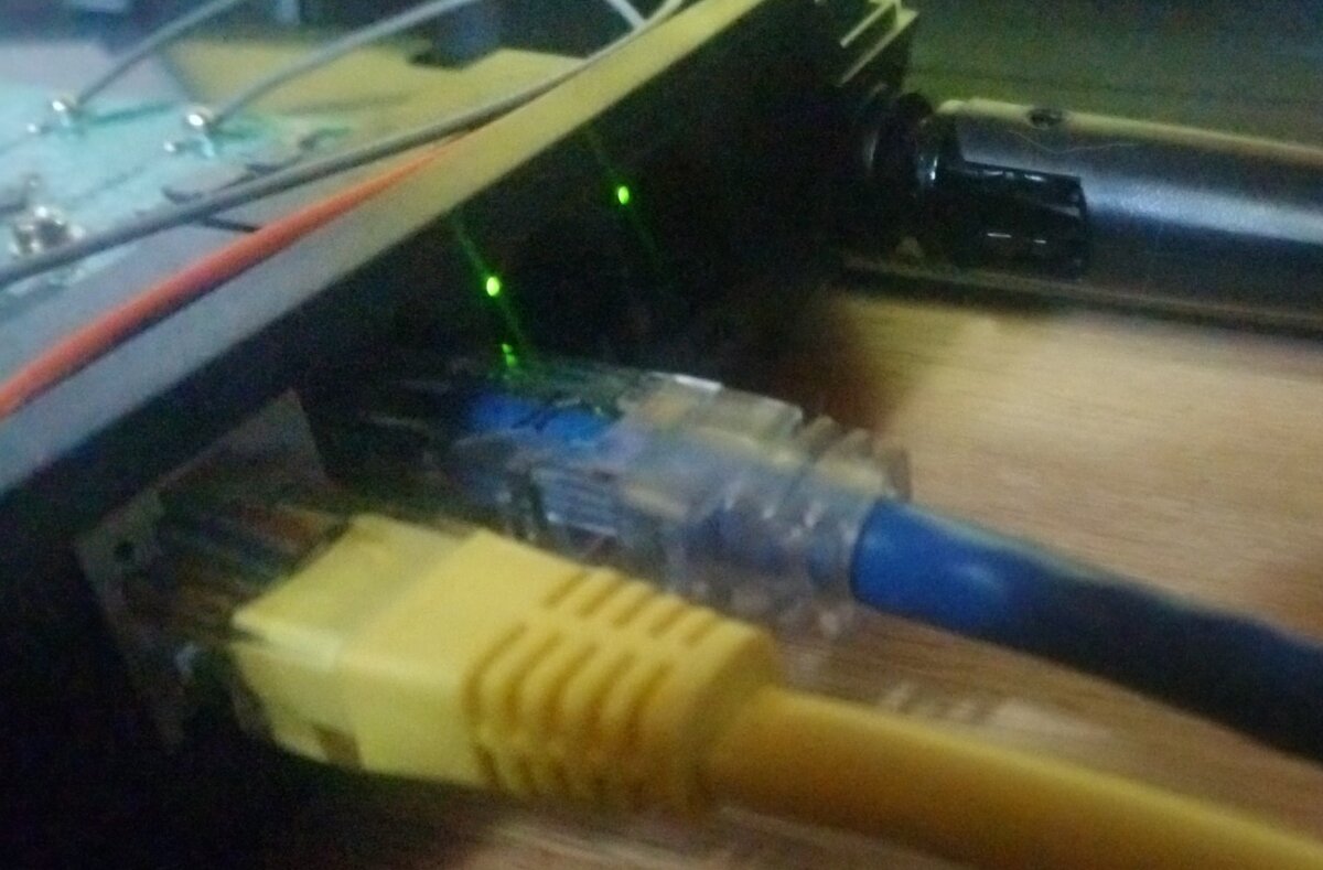
Two cables in, two LEDs on, no correlation between the two sets.
On 8 June the switch came up and passed traffic. Three weeks after the GPL drop.
Upstream: v1 to v6
I sent v1 on 10 June.
v1 never fully arrived. Patch 1/2 was rejected because my SMTP provider (Brevo, whose relay is visible in the Message-ID of that posting) had mangled the whitespace. Andrew Lunn's reply is short and to the point: it looks like my mailer had destroyed the whitespace in the patch, with a pw-bot: cr.
https://lore.kernel.org/netdev/aebccaad-eca3-4ea4-99dd-ae7edbc8981b@smtp-relay.sendinblue.com/
I switched to Resend and had to decide whether to repost immediately with an apology for the noise, or wait a day for someone to tell me what I already knew and then repost anyway. I reposted immediately, and got the answer to that question: netdev's bot asked for 24 hours between versions so reviewers in all time zones get a chance at the previous one, and Andrew said the same thing directly. Fair enough; the original mistake was mine for not checking what my provider did to outgoing mail.
https://lore.kernel.org/netdev/4d6e9d64-2a01-49be-ae2d-e4455ef63761@lunn.ch/
v2 is where the substance started. Luiz Angelo Daros de Luca had looked at the vendor firmware and concluded I did not need it. His argument: the firmware initializes the interface and then runs an infinite loop polling for link state changes, writing to exactly the same external interface force registers the driver already manages through phylink. Letting the DW8051 run gives you two entities controlling the switch, with the firmware setting the force registers behind the driver's back, which might go unnoticed in a strictly fixed-link topology but introduces races otherwise. The one thing the firmware does that matters is right after deasserting the SerDes reset: two writes to the SerDes BMCR register that trigger a data path reset and PLL resync, flushing the FIFOs and giving the link a clean cold start.
His recommendation was to drop the firmware loading entirely, port that reset sequence into the driver, and keep the 8051 disabled. He has been deep in this driver for a long time, so I did not second-guess it. I made the change, tested cold boots and reboots, and it worked without the firmware. The driver now holds the DW8051 in reset and clears its enable bit.
https://lore.kernel.org/netdev/CAJq09z4B_P7D0khof-e0hxu=A+UQYAH_anJYt8ppaFcjHCdBCw@mail.gmail.com/
An aside I only found while writing this post, four months after the fact: this was not the first attempt at the feature. In May 2022 Hauke Mehrtens sent a four-patch series adding SGMII and HSGMII to the same driver for the same chip, and it took the firmware route - the blob went in as an array in the driver, with MODULE_FIRMWARE("rtl_switch/rtl8367s-sgmii.bin") and a request_firmware() call. His cover letter says what he thought of the licensing:
This file does not look like intentional GPL. It would be nice if Realtek could send this file or a similar version to the linux-firmware repository under a license which allows redistribution. I do not have any contact at Realtek, if someone has a contact there it would be nice if we can help me on this topic.
Alvin Šipraga, the driver's author, offered to follow it up with Realtek and argued that absent any separate agreement the GPL notice on the vendor file governs anyway. That follow-up never lands in the thread. The series also arrived with two unsolved bugs of its own - wrong TCP checksums on transmit under one tag format, and receive-side offload mangling them under the other - and a long list of review comments about naming and about get_caps keying on the wrong property. No v2 was ever sent. The thread stops on 11 May 2022 and the feature stayed missing for four years.
So the route I was talked out of in v2 is the route that had already been tried, and the licensing question I avoided by dropping the firmware is the one that was still open when that series went quiet. Luiz was in that thread too, which puts his advice to me in a different light.
https://lore.kernel.org/netdev/20220508224848.2384723-1-hauke@hauke-m.de/
v3 dropped the firmware. Maxime Chevallier then pointed out that since I was already hinting at handling SGMII autonegotiation eventually, and my mac_link_up/mac_link_down paths were getting complicated by setting the external interface settings and then the SerDes settings, the whole thing would make more sense as a phylink PCS, and would be easier to maintain.
https://lore.kernel.org/netdev/63983efb-dcad-4b34-9d35-4086de11be5e@bootlin.com/
v4 is that conversion. The SerDes became a phylink_pcs handed over by mac_select_pcs(), with pcs_config, pcs_link_up, pcs_get_state and pcs_inband_caps. I did not implement pcs_enable, pcs_disable or pcs_an_restart: this is a fixed link, I could not test them, and implementing untestable code did not seem useful. In-band autonegotiation is not implemented either; pcs_inband_caps() reports that to phylink so it never selects an in-band mode for this PCS.
v5 brought two comments from Maxime and one problem that had nothing to do with the code. The comments: with pcs_inband_caps() implemented, phylink will only ever pass a valid negotiation mode, so my explicit -EOPNOTSUPP check was redundant; and did I actually know what the SerDes pause bits did in hardware, or was I copying the vendor? Both got resolved. I tested the pause bits by driving congestion toward a 100M user port and watching dot3OutPauseFrames on the CPU port track the SerDes TX/RX flow control bits, which showed those bits, and not the MAC force pause bits, are what gates pause on the SerDes external interface.
https://lore.kernel.org/netdev/e4e1d392-2430-4403-91b1-5be59d6a9895@bootlin.com/
The problem was that Resend rewrites the Message-ID, replacing mine with one of its own from Amazon SES. That breaks In-Reply-To across a series, so the tooling loses the thread. Mieczysław Nalewaj wrote to me privately to point out that Sashiko was showing my series as broken, which I would not have noticed otherwise. Presumably other bots, including private ones, were seeing it as incomplete too.
Mieczysław was also the one who told me that a group of people had been working on the same thing in parallel, in an OpenWrt pull request improving the Realtek DSA driver, with SGMII and HSGMII among the things being worked on. I had no idea. My initial research had not turned it up, and I want to be clear about the sequence, because it would be easy to assume otherwise: I did not base my work on theirs, and I did not know it existed until Mieczysław told me. It is still a draft. I regret not having found them earlier, because the implementation would have matured before it hit the list rather than during review. As it happened, both Luiz and Mieczysław ended up improving it on the list anyway.
https://github.com/openwrt/openwrt/pull/19644
v6 was sent with b4 send --web from my own domain, and is the version that got applied. It carries Reviewed-by tags and a Tested-by from Stanisław Pal, who ran the series on a TP-Link Archer AX55 v1: an RTL8367S with the SerDes on external interface 1 running HSGMII to an IPQ5018, on OpenWrt's 6.12 kernel, needing only the neg_mode parameter dropped from pcs_get_state() for the older phylink API there. The trunk comes up at 2.5 Gbps and passes traffic, with warm reboots and short power cycles clean every time, and no SerDes firmware involved.
https://lore.kernel.org/netdev/20260711-rtl8367s-sgmii-v6-0-88f7944ddca7@c127.dev/
https://lore.kernel.org/netdev/20260713081439.18379-1-stacho@venco.com.pl/
He also reported, in that same mail, one thing I could not reproduce:
One observation, quite possibly marginal silicon on my unit: after the device has been powered off for several hours, the first boot brings the link up (2.5Gbps/Full reported, phylink happy) but the data path is heavily degraded - 60-70% packet loss, the surviving packets at normal sub-ms RTT. Re-running the PCS sequence via admin down/up of the CPU port re-rolls the dice (15% and 40% loss on two consecutive attempts) but did not fully recover it; a soft reboot (full re-probe including the chip reset) always restores a clean link. Short power-offs (~a minute) do not reproduce this.
I tried to reproduce it on my board, cold and warm, and could not, so I could not help beyond saying so. What settled it was Stanisław's own work over the following week, on the list, and it is worth recording because the failure mode is a good trap.
The register state was not the answer. Dumping the switch through the regmap debugfs in the bad state and the healthy one gave byte-identical SerDes configuration - SDS_MISC (0x1d11) 0x1f00, SDS_OPTION (0x13c0/c1) 0x0000, external interface mode (0x1311) 0x1016, MISC_CFG0 (0x130c) 0x0043 - in both. Nor was it any single reset: SDS_RST, DW8051_RST, NIC_RST and GPH_RST applied to the bad state changed nothing at all, and the resets that did clear the counters also cleared the configuration, which makes them useless as evidence. Only a full re-probe ever recovered it.
The cause was the power supply. The A/B/A is unambiguous: the old supply failed on every cold morning across four documented occurrences, a new supply came up clean twice including a ten-hour soak, and putting the old supply back reproduced the exact signature again - link up at 2.5G full duplex with no CRC or symbol errors, 326 FCS errors and 326 drop events on the switch's CPU-facing port, nothing reaching the wire, and the switch-to-CPU direction byte-exact clean. Only the switch's SerDes receiver was affected. In hindsight the earlier partial fixes fit: a 180-second delay before init "worked" because it gave the supply three minutes to come up, and short power cycles never reproduced it because the capacitors had no time to discharge.
https://lore.kernel.org/netdev/20260722082321.13802-1-kuncy7@gmail.com/
The rate limiters are a separate story that came out of the same review. Mieczysław reported that performance degradation without setting certain registers only shows up in HSGMII mode with simultaneous load on multiple LAN ports, which had been found during work on adding MR85X support to OpenWrt, where several clients on gigabit user ports were capped at about 1.02 Gbps combined until those limiters were raised, after which throughput reached around 2 Gbps. Those measurements were made on their code, not mine. I verified the same register from the other direction, because my SoC cannot push more than a gigabit anyway: I lowered the port 6 limiter to 100 Mbps at runtime and watched iperf3 clamp to exactly that in each direction while the link still negotiated 1 Gbps, then restored it. The chip resets these to a default that works out to roughly 1.048 Gbps, which caps aggregate HSGMII throughput at about a gigabit; the vendor documentation describes that reset value as disabling the limiter, but the cap is real on hardware. The vendor's own switch init raises them unconditionally, and so does the driver now.
https://github.com/openwrt/openwrt/pull/19445#issuecomment-4505613294
One thing I would fix if there had been a v7 is wording, in two places. The v6 cover letter says the configuration sequence and SerDes tuning parameters are "derived from" the GPL-licensed Realtek vendor driver, and the in-tree comments on both jam tables say the values are "lifted from the vendor driver sources". Read literally, both suggest the values were copied out of those files. What actually happened is described above: the values were captured on the bus, and the vendor sources were consulted afterwards only to identify what they were. The series was already applied by the time I wanted to reword it.
Full 2.5 Gbps line rate throughput remains unverified on my hardware. The HSGMII link is confirmed running at 2.5G at the register level, on both the SoC uniphy mode and the GMAC clocks, but the SoC side is driven by the IPQ5018 SSDK and the user-facing PHYs are gigabit, so there is no way for me to generate enough traffic to prove it end to end. The RTL8367SB declares both modes in its chip info entry as well and the vendor driver drives both chips through the same code path, keyed only on the chip option register, so it is expected to work there too, but I have no RTL8367SB hardware to confirm it.
Aside: sending patches over SMTP
This is not about the driver, but it cost me two revisions, so it is worth writing down for anyone sending their first series.
Brevo mangled patch whitespace, which killed v1. Resend fixed that but rewrote the Message-ID, which broke thread correlation for the bots across v2 through v5. Neither problem is visible from the sending side; both were reported to me by other people.
The second one is still legible in the archive. The v2 to v5 postings sit under @email.amazonses.com Message-IDs, but their References headers point at the @c127.dev IDs my own tooling generated - 20260610084120.1100326-1-contact@c127.dev, 20260613232136.24246-1-contact@c127.dev, 20260702204648.276112-1-contact@c127.dev. Those messages do not exist anywhere, because nothing was ever delivered under those IDs. Anything walking the thread by Message-ID follows those references into nothing.
I looked at a linux.dev address, which I liked, but the format is name plus surname at the domain, and I did not want to lose the alias I use. I tried a Google trial and used it for exactly one reply on v6, but the pricing is per account and aimed at businesses with tooling I have no use for. I settled on Purelymail, which is about 4 USD a year plus per-message cost, configured SMTP against my own domain, and have not had a problem since.
Current status
Both patches are merged into net-next and are expected in 7.3:
- SGMII: https://git.kernel.org/pub/scm/linux/kernel/git/netdev/net-next.git/commit/?id=0b577e2fe06c023ab996c3d7684538dbbf6e99bc
- HSGMII: https://git.kernel.org/pub/scm/linux/kernel/git/netdev/net-next.git/commit/?id=987137345f3312fd68cc9c11bd46b754bfb0046f
Merged 22 July 2026, 619 lines added to drivers/net/dsa/realtek/rtl8365mb_main.c.
Open: 2.5 Gbps line rate, unverified on my hardware; the RTL8367SB, expected to work and untested; and in-band autonegotiation, which would need pcs_get_state() to do real work rather than reporting a forced link. The cold boot degradation is closed - a failing power supply on the reporter's unit, not the driver.
The MR80X v2.20 board support itself is not upstream yet. My order for that is: publish the seven-day radio test results, put up a test image so other people can confirm it works, and then submit the board support. The reduced ath11k ring sizes are the sticking point, since OpenWrt's position is that they support devices with 512 MB of RAM or more, and that is a case I have to make with data rather than with a patch.